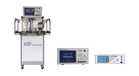
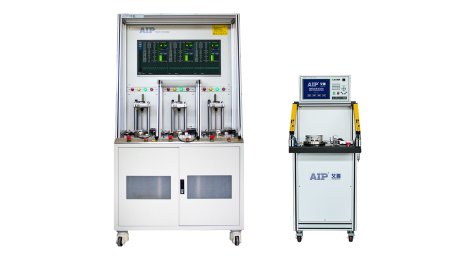
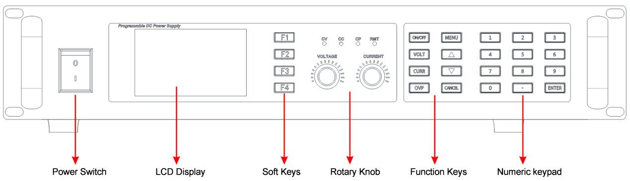
Convenient panel operation. This series of products uses a 2U standard chassis, which is suitable for both workbench operation and convenient installation in industrial standard cabinets. It is equipped with a high-brightness 4.0-inch color LCD display, comfortable silicone buttons, easy-to-use knobs, and 4 intuitive LED status indicators.
Abundant built-in interfaces
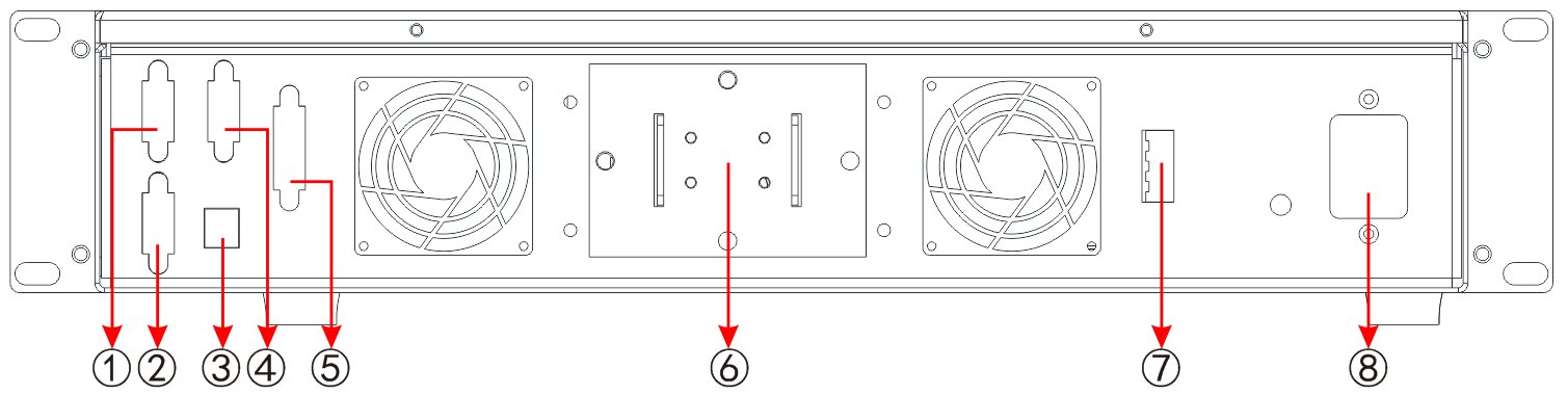
① Parallel interface - from
② Parallel Interface - Main
③ USB interface
④ RS232/RS485/CAN interface
⑤ Remote analog control interface
⑥ Power output terminal
⑦ Remote S-compensation terminal
⑧ Power input terminal
DC output
This series of power supplies includes three basic models: 750W, 1.5kW, and 3kW, with output voltages ranging from 0 ~ 10V to 0 ~ 2000V and output currents from 0~ 2.5A to 0~ 500A, corresponding to various models. Whether manually or remotely controlled (analog or digital), voltage, current, and power can be continuously adjusted between 0% and 100%.
Power absorption function
The AIP53 series power supplies feature power absorption: when a power supply is connected to a motor-type load and the power supply stops outputting power, the inductive load (motor) does not immediately disappear. Instead, the motor becomes an energy source, charging the power supply. The AIP53 series power supplies have an internal power absorption module that can instantly absorb this energy, preventing overvoltage damage to the power supply's filtering components.
Parallel operation function
All products come standard with a digital master-slave bus. This allows up to 10 identical products to be connected in parallel, aggregating actual voltage, current, and power to form a larger system. The entire master-slave system configuration can be completed via the product's control panel or remotely via any digital communication interface.
Remote compensation function
To avoid voltage drop caused by excessively long connecting wires, remote testing allows for direct measurement of the output voltage at the terminals of the device under test (DUT), thus improving measurement accuracy. S+ and S- are remote compensation terminals; when using remote compensation testing, simply connect S+ and S- to the positive and negative terminals of the DUT.
Discharge circuit
All power supply units in this series are equipped with internal discharge circuits. Under no-load or light-load conditions, it ensures that dangerous voltage drops below 10VDC within 1 second after the DC output is turned off, ensuring human safety.
Analog control interface (optional)The product's rear panel features an isolated analog interface terminal. Connecting 0-10V or 0-5V to the analog input pins allows setting the output voltage, current, and power from 0-100 %. The analog output pins output 0-10V or 0-5V, corresponding to 0-100 % of the output voltage and current, enabling output voltage and current monitoring. Additionally, several input and output pins are available for controlling and monitoring the product's status.
Protection function
To protect the customer's connected devices, an overvoltage protection limit (OVP), as well as overcurrent (OCP) and overpower (OPP) protection limits can be set for the product. If any of these three values are exceeded for any reason, the DC output will be immediately cut off, and a status signal will be sent to the display and interface. This product also has overtemperature protection; if the product overheats, it will shut down the DC output to ensure the safety of the device under test and the power supply.
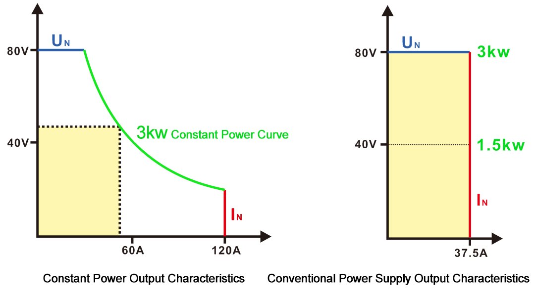
Wide range outputConstant power supplies offer a wider output voltage and current range compared to ordinary power supplies, and a single model can meet the testing needs of customers with various product specifications. The output voltage and current of a power supply are limited by its maximum power rating; reducing the output current can achieve a higher voltage, or vice versa, making it more flexible than traditional "matrix" power supplies. (See diagram below.)
Function generatorAll models in this series feature a true function generator capable of generating typical functions and applying them to output voltage or output current. The generator can be set via the front panel or remotely configured via a digital interface. Preset functions provide the user with all necessary parameters, such as Y-bias value, time, frequency, or amplitude, along with a complete set of configuration parameters.

Output reverse voltage protection (optional)
Because inductive loads generate back electromotive force at the instant the power is switched on or off. The peak voltage of this type of voltage is far greater than the voltage that the load power supply can withstand, which can easily cause power supply failure. The traditional solution is for the customer to connect a diode in parallel at the power supply output, which is complicated by wiring, difficult to select, and has very low practicality. However, the AIP53 series DC power supply can integrate a reverse voltage protection module internally to absorb the reverse voltage generated by inductive loads. This eliminates the need for the customer to connect a diode in parallel externally, simplifying wiring and diode selection.
Sequence testing
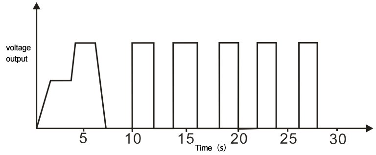
In addition to standard functions generated by the function generator, it can also form some complex functions. The sequence test function contains 50 sequences, stored in non-volatile memory. Each group contains 20 test steps. Users can edit the function of each step according to actual needs, so that the power supply can output in a sequence in constant voltage, constant current, or constant power mode to meet specific test requirements.Sequence test examples
A typical aging test process is as follows: First, a voltage is applied to the test object at a certain slope for a period of time. Then, the voltage is suddenly increased to another level and held for a period of time. This process is repeated, and finally, the voltage is reduced to zero at a certain slope. In some cases, a voltage switching cycle test sequence is also required. The following figure shows a voltage waveform for an aging test.
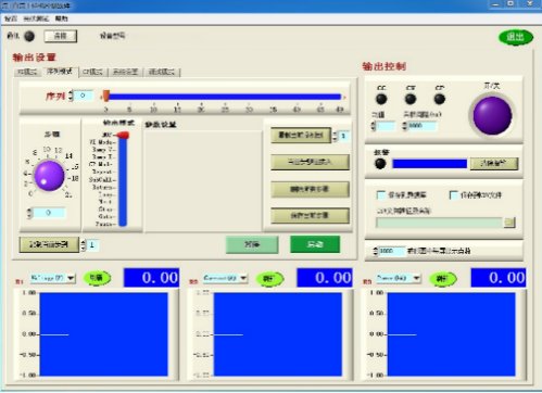
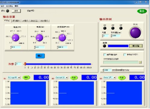
Industrial control computer softwareThis product also comes with control software suitable for Windows systems, allowing remote control of multiple units of the same model. It features a clear main interface displaying all set and actual values. It also includes functions such as remote start/stop, data saving, and sequence test programming.
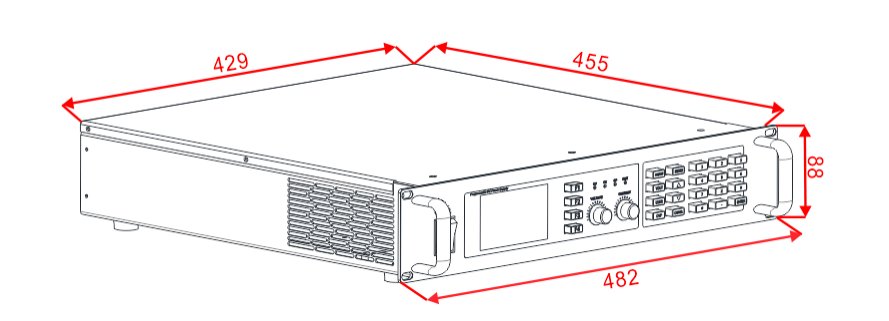
Chassis mounting dimensions diagram
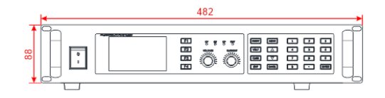
Front panel opening dimensions diagram
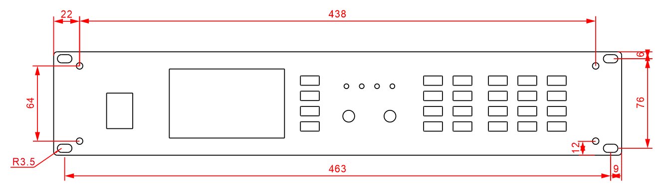
Note: A shortened version with or without handles is available for the front panel, meaning the front panel length can be the same as the chassis length.
AIP53 Series (1.5kW) Selection (Supports Parallel Operation )
Model
| AIP53-01500 -10-250 | AIP53-01500 -20-160
| AIP53-01500 -35-110
| AIP53-01500 -40-60
| AIP53-01500 -60-75
| AIP53-01500 -80-60
|
| AC input | Number of phases | 1ph+N+P |
| Voltage | 220VAC±10% |
| Frequency | 45~66Hz |
| Power factor | ≥0.99 |
| DC output | Power | 0~1500W |
| Current | 0~250A | 0~160A | 0~100A | 0~60A | 0~75A | 0~60A |
| Voltage | 0~10V | 0~20V | 0~35V | 0~40V | 0~60V | 0~80V |
| Efficiency | ≤92% | ≤92% | ≤92% | ≤92% | ≤92% | ≤92% |
| Programming precision | Voltage | ≤±(0.03%+0.02%FS) |
| Current | ≤±(0.05%+0.05%FS) |
| Power | ≤±0.4%FS |
| Readback accuracy | Voltage | ≤±(0.03%+0.02%FS) |
| Current | ≤±(0.05%+0.05%FS) |
| Power | ≤±0.4%FS |
| Ripple and noise | RMS | 10mVrms
|
| (20Hz-300kHz) |
| PP | 100mVpp |
| (20Hz-20MHz) |
| Source effect | Voltage | ≤0.02%FS (±10%ΔUAC input) |
| Current | ≤0.05%FS (±10%ΔUAC input) |
| Load effect | Voltage | ≤0.05%FS (0-100% load regulation) |
| Current | ≤0.15%FS (load regulation rate of 0-100%ΔUDC) |
| Analog interface (optional) | Specification | Built-in 15-pin D-Sub female connector, electrically isolated |
| Signal range | 0~5V or 0~10V (switchable) |
| U / I / P accuracy | 0~10V: ≤0.2%FS 0~5V: ≤0.4%FS |
| Dynamic response time | Load adjustment takes time | ≤2ms (load adjusted from 10-100%) |
| Output voltage rise time | Maximum 10ms (10~90% of full scale) |
| Protection function | OTP, OVP, OCP, OPP, PF |
| Communication interface | RS232 + LAN (standard) RS485/USB (optional) |
| Work environment | Operating temperature: 0~50℃, humidity: <80%, non-condensing, storage temperature: -20~70℃, altitude: <2000m |
| Isolation and withstand voltage | 1000VDC (output to ground) |
| Volume W × D × H (mm) | 482×455×88 Standard 2U Chassis | 482×455×88 Standard 2U Chassis |
| Packaging volume W × D × H (mm) | 668×665×220 |
| Weight/Weight including packaging | 11.5kg/15.3kg | 10.8kg/14.6kg |
| Model | AIP53-01500 -100-50
| AIP53-01500 -200-25
| AIP53-01500 -360-15
| AIP53-01500 -500-10
| AIP53-01500 -750-7
| AIP53-01500 -1000-5 |
| AC input | Number of phases | 1ph+N+PE |
| Voltage | 220VAC±10% |
| Frequency | 45~66Hz |
| Power factor | ≥0.99 |
| DC output | Power | 0~1500W |
| Current | 0~50A | 0~25A | 0~15A | 0~10A | 0~7A | 0~5A |
| Voltage | 0~100V | 0~200V | 0~360V | 0~500V | 0~750V | 0~1000V |
| Efficiency | ≤93% | ≤93% | ≤93% | ≤93% | ≤93% | ≤93% |
| Programming precision | Voltage | ≤±(0.03%+0.02%FS) |
| Current | ≤±(0.05%+0.05%FS) |
| Power | ≤±0.4%FS |
| Readback accuracy | Voltage | ≤±(0.03%+0.02%FS) |
| Current | ≤±(0.05%+0.05%FS) |
| power | ≤±0.4%FS |
| Ripple and noise | RMS | 20mVrms | 20mVrms | 40mVrms | 50mVrms | 50mVrms | 100mVrms |
| (20Hz-300kHz) |
| PP | 175mVpp | 175mVpp | 250mVpp | 325mVpp | 325mVpp | 650mVpp |
| (20Hz-20MHz) |
| Source effect | Voltage | ≤0.02%FS (±10%ΔUAC input) |
| Current | ≤0.05%FS (±10%ΔUAC input) |
| Load effect | Voltage | ≤0.05%FS (0-100% load regulation) |
| Current | ≤0.15%FS (load regulation rate of 0-100%ΔUDC) |
| Analog interface (optional) | Specification | Built-in 15-pin D-Sub female connector, electrically isolated |
| Signal range | 0~5V or 0~10V (switchable) |
| U / I / P accuracy | 0~10V: ≤0.2%FS 0~5V: ≤0.4%FS |
| Dynamic response time | Load adjustment takes time | ≤2ms (load adjusted from 10-100%) |
| Output voltage rise time | Maximum 10ms (10~90% of full scale) |
| Protection function | OTP, OVP, OCP, OPP, PF |
| Communication interface | RS232 + LAN (standard) RS485/USB (optional) |
| Work environment | Operating temperature: 0~50℃, humidity: <80%, non-condensing, storage temperature: -20~70℃, altitude: <2000m |
| Isolation and withstand voltage | 1000VDC (output to ground) |
| Volume W × D × H (mm) | 4 82×455×88 Standard Chassis 2U |
| Packaging volume W × D × H (mm) | 668×665×220 |
| Weight/Weight including packaging | 10.8kg/14.6kg |