Flat wire motor winding technology background
With the development of high-performance, high-efficiency, and high-power density automotive drive motors, flat-wire motors have gradually become the target of new energy vehicle drive motors due to their high slot fill rate, high heat dissipation efficiency, and good NVH characteristics.
The application of flat wire motors in new energy vehicles started from the "Advanced Integrated Drive System (DOE)" project led by the US Department of Energy. The motor of this project uses three key technologies, one is five-phase winding, the other is dual V magnetic pole structure, another item is the flat wire motor. During the initial exploration phase of the project, two options were developed. One is the wave winding + open slot scheme, which uses radial wire insertion, and the other is the axial wire insertion technology, where the windings are inserted from the end face of the stator. The two schemes have their own advantages and disadvantages. The radial inserting wire needs to use an open slot, which will increase the cogging harmonics and the eddy current loss; the axial inserting wire is easy to insert the wire, but the welded end needs to be twisted and formed after insertion. There are also many welded joints.
In 2011, the DOE project was completed, and the first Chevrolet model equipped with a flat wire motor was also released. Different from ordinary round wire motors, such as (Figure 1.1), this motor adopts the hairpin winding technology of axial insertion, and adopts a semi-closed parallel slot structure.
In 2011, the DOE project was completed, and the first Chevrolet model equipped with a flat wire motor was also released. Different from ordinary round wire motors, such as (Figure 1.1), this motor adopts the hairpin winding technology of axial insertion, and adopts a semi-closed parallel slot structure.


This kind of hairpin needs to be inserted first, and then a twisting device is used to twist one end of the opening into a structure similar to "frog feet", weld different frog feet together, and finally wrap it with epoxy resin (Figure 1.2) to achieve insulation. Enhanced, this technology reduces DC resistance by 30~40%.


Figure 1.2
Although the DC resistance is reduced, it has drawbacks:
Winding produces skin effect and proximity effect at high frequencies. As the rotational speed increases, the AC resistance of the winding increases, and even exceeds the resistance of the round wire scheme. For example (Figure 1.3) the resistance of the round wire scheme is 1.44 times that of the DC resistance of the flat wire. But when the motor speed increases and the frequency increases, the AC resistance of the flat wire increases, exceeding the round wire resistance at 8000rpm.


Figure 1.3
2. The flat wire close to the slot will generate a large eddy current loss, which will cause heat accumulation and form local heat conduction. Such as (Figure 1.4)


Figure 1.4
In order to improve the above defects, further optimizations were made in the subsequent Chevrolet Spark in 2014 and Chevrolet Blot in 2017, such as (Figure 1.5, 1.6), which will not be discussed here.

Figure 1.5


Figure 1.6
Types and processes of flat wire motors
1.According to the manufacturing process

2.By winding method
(1) Wave winding (2) Laminated winding (3) Concentrated winding
3.By layers
4pin, 6pin, 8pin, 10pin, odd pins
4.Manufacturing Process of Flat Wire Winding Stator
1) Hair-Pin (as shown in Figure 2.1)
Insert insulating paper → hairpin forming → wire insertion → end separation (flare) → twist head → welding → paint dripping/powder coating → electrical measurement
2) I-Pin
Insert insulating paper → insert wire → end separation (flare) → twist head → welding → drip paint/powder → electrical test
3) Continuous wave winding
Insert insulating paper → wire forming / braiding → lowering wire → slot wedge → dripping paint → electrical test

Summarize:
The biggest difference between Hair-pin and I-pin is that there is one more step of hairpin forming. Hair-pin needs to be formed into a U shape first by splitting, punching or bending. We call the forming end as the crown end and the other end as the welding end. However, both ends of the I-pin are welded ends. Since the welding will take up additional radial dimension, when the I-pin is connected in series and parallel to each pole phase group, an opposite pin will be generated at one end to occupy the radial dimension, resulting in one end of the winding exceeding the stator. The inner diameter thus allows the rotor to enter the shaft only from the regular end. However, the advantage of I-pin is that the process from plugging the wire to welding is relatively easy, while the position of the wire after the hair-pin plugging is extremely demanding, making it difficult to shape. Moreover, the I-pin does not need to be formed, and the test for the patent leather is relatively small, and the flattening rate of the flat wire can be made large to reduce the skin effect of the flat wire.
Flat wire winding structure principle
Windings are the main components that make up the motor. The motor generates electromagnetic power and electromagnetic torque by inducing the potential in the winding and the current through the winding, so as to achieve the purpose of energy conversion. Different winding structure parameters such as the number of winding turns, conductor cross-section, spatial distribution, connection method, insulation grade, etc., reflect different electromagnetic properties and performance indicators. Therefore, to analyze the principle and operation of the flat wire motor winding structure, it is necessary to have a basic understanding of the winding composition and connection laws.
1.Winding classification
(1) According to the number of coil layers: single-layer winding, double-layer winding, single-layer winding, multi-layer winding (flat wire 4pin, 6pin, 8pin, etc.)
(2) According to the number of slots per pole per phase q: integer slot winding, fractional slot winding
(3) According to the winding method: stacked winding, concentric winding, wave winding, chain winding, cross winding
2.Winding composition principle
(1) The principle of maximum potential superposition: Under a certain number of conductors, the potential and magnetic potential of the synthesized fundamental wave (working wave) are the largest. Specifically, the fundamental wave potential and magnetic potential synthesized by the two coil sides of a single coil are the largest;
(2) The principle of minimum non-working harmonics: Under a certain number of conductors, the combined magnetomotive force and electromotive force of the windings strive to be close to sinusoidal in waveform, and strive to obtain larger fundamental wave magnetomotive force and electromotive force (larger winding coefficient), Keep the harmonic content as low as possible
(3) Symmetry principle: the number of slots occupied by each phase winding and the number of conductors connected in series should be equal, and the resistance and reactance of each phase should be balanced. The total number of slots of the armature must be divisible by the number of phases, that is, Z1/m = integer. For multi-phase windings, the electromotive force and magnetomotive force of each phase should be symmetrical, and the resistance and reactance should be balanced.
(4) Economic principle: The electric potential and magnetic potential generated by the windings are only related to the connected conductors and have nothing to do with the connection order. Therefore, the amount of copper used in the windings should be saved, the resistance is small, and the loss is small.
(5) Technological principles: reliable insulation and mechanical strength, good heat dissipation, and convenient winding manufacturing, installation, and maintenance
3.Comparative analysis of winding structure and drawing method
Taking the most common three-phase 48-slot 8-pole motor for driving motors as an example, let's first look at the drawing method of single-layer or double-layer windings of ordinary motors:
(1) Basic data of motor winding: m=3, Z=48, 2p=8
(2) Calculate the number of slots per pole and phase: q=48/8/3=2
(3) Draw a star diagram of the tank potential
In the inner circumference of the stator, the six slots are numbered (1#~48#) in sequence according to the rotation direction of the rotor, as shown in (Figure 3.1);
The stator slots are distributed within the electrical angle of p•360º, and the phase difference of the induced potential of the conductors in the adjacent two slots is an electrical slot pitch angle, the electrical slot pitch angle α=360/Z*p=360/48*4= 30º, the phase of the induced potential of the conductors in the adjacent two slots is different by 30º electrical angle. The potential of each slot is represented by a phasor diagram as shown in Figure 3.2, which is called the slot potential star diagram.

The star diagram of the slot potential reflects the phase relationship of the induced potential in each slot conductor. According to the star diagram, it is found that the phases of the induced potentials in the 1#, 13#, 25#, and 37# slots are the same, so we can see the 8-pole 48-slot motor as It consists of four 2-pole 12-slot unit motors.
(4) Phase band division: As shown in Figure (3.3), for the three-phase winding, the average phase band of each phase is 180º/3=60º. Of course, the actual phase band can vary in size, but the average phase band is still 60º. That is to say, not all wires in slots 1#, 13#, 25#, 37#, 2#, 14#, 26#, and 38# are U-phase. Some conductors are phase shifted by 1 to 2 slot pitches.
(5) The composition of the winding
Single layer winding
Single-layer windings are generally only used for small-capacity motors. The winding process is simple, and the full rate of no interlayer insulation slots is high. However, the winding waveform is not sinusoidal enough, and the iron loss is noisy. For a 48-slot 8-pole motor, the number of slots per pole and phase is q=2, so the inner conductors of the two slots (1# and 2#) in the U-phase belt are respectively connected with the two slots (7#) in the -U-phase belt. # and 8#) inner conductors are connected to form a single coil, but here are three options:
A-stack winding (cross winding)
For example (Figure 3.4) the pitch of two single coils is equal, also called equal winding, the ends of the two coils are stacked one on top of the other, so it is called a stacked winding.
Since there is a phase difference in the potentials in the two single coils of the stacked winding, the two cannot be connected in parallel and must be connected in series. Therefore, each phase of this connection method can only form one pole phase group. This winding method has a total of 4 pole phase groups, so the maximum parallel connection The number of branches is 4. Winding expansion diagram (Figure 3.5), winding potential diagram (Figure 3.6). (Fig. 3.7) According to the simulation, the ampere-turn value of the fundamental wave magnetomotive force generated by the single-turn coil is 1.22. (Fig. 3.8) According to the simulation, the fundamental wave winding factor = distribution coefficient * short distance coefficient 1 = 0.9659.


B Concentric winding:
For example (Figure 3.9) the pitches of the two single coils are different, the coils 2-7 are a short-pitch coil, and the coils 1-8 are a long-pitch coil, and the two form a shape like concentric circles, so it is called It is a concentric winding.
The two single coils of the concentric winding have a short pitch Y1=5 and a long pitch Y1=7, but the average span is still 6. Therefore, the ampere-turn value of the fundamental wave magnetomotive force generated by the single-turn coil of this winding method is 1.22, and the fundamental wave winding factor 0.9659 is the same as that of the stacked winding. Although the potential phase is the same and the size is the same, due to the different end spans of the two coils, the DC resistance and end leakage reactance of the two coils are different, and they can only be connected in series but not in parallel. The maximum parallel branch The number is also 4. Winding expansion diagram (Figure 3.10), winding potential diagram (Figure 3.11). Because the potential and magnetic potential generated by the winding are only related to the connected conductors, and have nothing to do with the connection order.

C Chain Winding:
As shown in Figure (3.12), the pitches of the two single coils are the same, the coils 2-7 are short-distance coils, and the coils 1-8 are also short-distance coils, but the ends of the coils are bridged with those of coils 2-7. Instead, the two form a shape like a chain ring, hence the name chain winding.
The two single coils of the chain winding are exactly the same, and they are all short-distance coils, the pitch is Y1=5, the potentials are the same, the phases are the same, the DC resistance and reactance are also the same, they can be connected in series or in parallel. Therefore, the maximum number of parallel branches in the winding method is 8. Moreover, this connection method is shorter than the first two types of winding end spans, so the amount of copper used at the end of this winding will be small, which can save costs, so our most common single-layer winding also uses this winding method.

Double-layer winding
Two coil element sides are embedded in each slot of the core slot of the double-layer winding. When one coil side of the coil element is embedded in the upper layer of a certain slot, the other coil side is placed in the upper layer of another slot. Therefore, the total number of coils in the double-layer winding is equal to the total number of slots.
Since it is a double-layer winding, there are two layers of conductors in one slot, so there are many choices of pitch. When the pitch is equal to the pole pitch, the fundamental wave potential obtained by the coil is the largest, at this time Y1=τ; but according to the principle of minimum non-working harmonics, Y1=τ is not the best choice, because the induction obtained by this choice is The potential usually has large harmonics, so a short distance is usually used, that is, it is appropriate to select Y1<τ and Y1≈τ. When Y1≈ (5/6) τ, the fifth and seventh harmonics can be effectively weakened at the same time. . The following are examples of short-distance windings.
A stack winding
The winding method is similar to that of a single laminated winding. If one coil side of a coil is placed on the upper layer of the 1# slot (referred to as the upper side), the other coil side is placed on the lower layer of the 6# slot (referred to as the lower side); the upper side of the coil is placed on the 2# slot. For the upper layer, the side of the lower layer is placed on the lower layer of the 7# slot; by analogy, a total of 48 single coils can be formed. It can be found that when short-distance winding is used, not every slot has the same phase conductor. For example, the upper layer of No. 2 slot is U phase but the lower layer is -W phase, so the interlayer insulation problem needs to be considered when using short distance. For example (Fig. 3.13), then connect the 2 coils in the same slot in the same phase band under each pole in series, and the tail end of the 6# coil is connected to the head end of the 2# coil, thus forming a pole phase group; 8 pole phases The groups can be connected in series or in parallel, so the maximum parallel branch is 8. The more parallel branches and the more wire ends and wire tails, the more complicated the process. Finally, we connect the end of the UVW line to a star or a corner, and the in-phase line ends go out in parallel to form the completed winding.

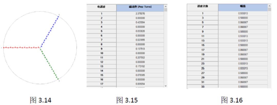
Double-layered winding: The winding potential diagram is shown in Figure 3.14, as shown in Figure 3.15. Because it is a double-layer winding, the single-turn winding MMF should be 2.375/2=1.1875, which is slightly smaller than the single-layer winding single-turn MMF of 1.21. This also cites the principle of maximum potential superposition mentioned earlier. As shown in Figure 3.16, the winding coefficient of 0.933 is slightly smaller than the single-layer winding coefficient of 0.965, but the 5/7th harmonic 0.066 is also much smaller than the single-layer winding 0.258.
B wave winding
A wave winding is any two coils in series that travel like a wave in the direction of the wire. The main feature is that a coil is connected in series with the coils under the adjacent magnetic poles of the same sex. We use the synthetic pitch Y to represent the connection law of the wave winding, and the synthetic pitch Y refers to the number of slots that advance along the winding direction for each coil winding connected in series. Since the wave winding is to connect the lower coils of the same pole in series, each time advances about a pair of pole pitch (2τ), for the integer slot wave winding, the composite pitch y is usually selected as a pair of pole pitch (Z/p). However, when the composite pitch is selected in this way, after the windings are connected in series with p coils (wound around the stator for one week), the windings will return to the original slot number and close by themselves. It is also impossible to connect the coils belonging to the same phase. In order to connect all the coils belonging to the same phase, after each turn, it is necessary to artificially advance or retreat a slot, so that the winding can continue to be wound.
In this example: the span on both sides of the same coil is Y1=5, the span from the tail end of the previous coil to the head end of the next coil is Y2=7, and the combined pitch Y=pole pitch 2τ=48/4=5+7=12.
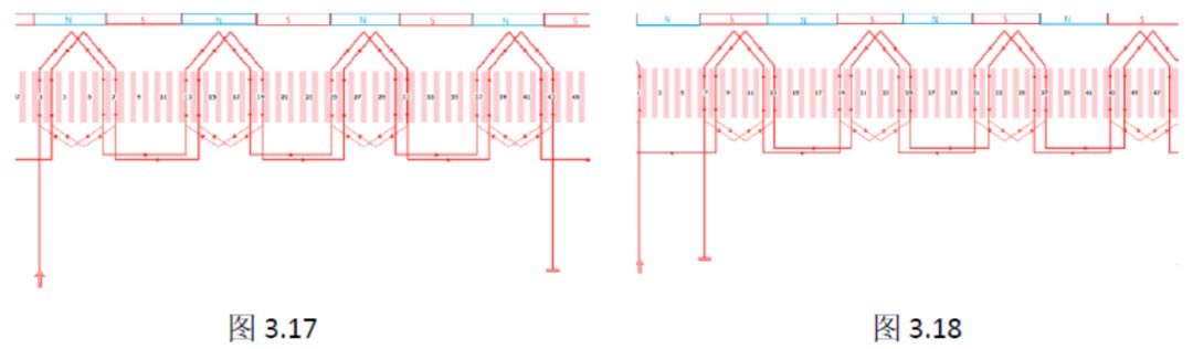
As shown in (Figure 3.17) branch 1, the series sequence of the coils under the U-phase N pole is as follows:
(1#upper-6#lower)-(13#upper-18#lower)-(25#upper-30#lower)-(37#upper-42#lower) (2#upper-7#lower)-( 14#Upper-19#Lower)-(26#Upper-31#Lower)-(38#Upper-43#Lower)
As shown in (Figure 3.18) branch 2, the series sequence of the coils under the U-phase S pole is as follows:
(1# lower layer-44# upper layer)-(37# lower layer-32# upper layer)-(25# lower layer-20# upper layer)-(13# lower layer-8# upper layer)
(48# lower layer-43# upper layer)-(36# lower layer-31# upper layer)-(24# lower layer-19# upper layer)-(11# lower layer-7# upper layer)
When Y=2τ is adopted for the wave winding, the connection rule is: the winding circles q circles along the armature surface, and all the coils of the N-pole subordinate phase on the upper side are connected in series in a certain order to form half of the phase winding, and then along the The surface of the armature is wound around q circles, and all the coils belonging to the same phase under the S poles on the upper side are also connected in series according to the same rule to form the other half of the phase winding. The two halves can be connected in series or in parallel. When they are connected in series, a=1 is obtained, and if they are connected in parallel, a=2 is obtained.
It should be noted that the connection rule of the double-layered winding is to connect the in-phase coils under one pole in series to form a pole-phase group, and each phase of 8 poles can form 8 pole-phase groups, so the maximum number of parallel branches of the stacked winding is is 8. While the coils under the same pole of the wave winding are connected in series with each other, when Y=2τ is adopted, each phase can only form two pole-phase groups.
But it is not that the maximum number of parallel branches of the wave winding can only be 2. When Y=2τ+1 is adopted, 2p(8) parallel branches can be obtained.
Such as (Fig. 3.19) (Fig. 3.20): Y1=7, Y2=6, composite pitch Y=7+6=13.
Branch 1: Branch 2:(1#upper layer-8#lower layer)-(14#upper layer-21#lower layer) (27#upper layer-34#lower layer)-(40#upper layer-47#lower layer)
Branch 3: Branch 4:(13#upper-20lower)-(26#upper-33#lower) (39#upper-46#lower)-(4#upper-11#lower)
Branch 5: Branch 6:(25# upper layer-32 lower layer)-(38# upper layer-45# lower layer) (3# upper layer-10# lower layer)-(16# upper layer-23# lower layer)
Branch 7: Branch 8:(37# upper layer-44 lower layer)-(2# upper layer-9# lower layer) (15# upper layer-22# lower layer)-(28# upper layer-35# lower layer)
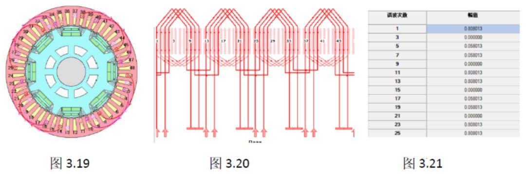
Although the long-distance winding Y1=7 and the synthetic pitch Y=6 can be used to change the wave winding to 8 parallel connections, the phase of each conductor in the slot changes, resulting in a winding coefficient of only 0.808.
C-stack winding vs. wave winding
The copper at the ends can be saved when the stacking winding is short-distance, but there are many connections between the coil groups (pole-phase groups) (referred to as inter-pole connections). Due to the large number of inter-pole connections, the end lead lines are arranged. Rather messy. The last few coils are difficult to rule when ruled.
The synthetic pitch of the wave winding Y=Y1+Y2≈2τ, when Y1 decreases, Y2 must increase, that is, when one end is shortened, the other end must increase, so the short distance cannot save copper at the end. The coil of the wave winding is usually a single-turn coil, and there are fewer connections (referred to as inter-pole connections) between the coil groups (pole-phase groups), so the lead lines are arranged neatly and beautifully.
Four-layer flat wire winding
The winding method of four-layer windings is similar to that of double-layer windings. Conventional windings are also divided into stacked windings and wave windings. Some manufacturers also make special windings such as concentric windings, same-layer windings, and overlapping wave windings, etc. This will be described below. One article analyzes the patents of each factory one by one. This chapter only describes the general winding method. Take 8 poles and 48 slots, and the full-pitch winding Y1=6 as an example.
A stack winding
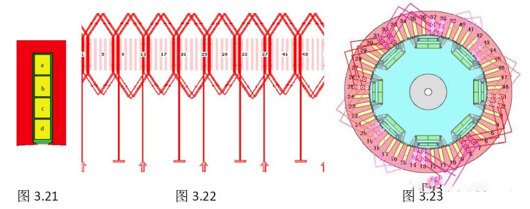
For example (Fig. 3.21) (Fig. 3.22), the four-layer winding can be regarded as a double-layer winding with 2 turns. The winding method is the same as that of the double-layer winding. The outermost to the innermost conductors are respectively a/b/c/d. Two in-slot coils in the same phase band under the pole are connected in series to form a pole phase group, and the maximum number of parallel branches is 2p=8. Such as (Figure 3.23) when using the full-pitch winding,
All conductors in a slot have the same phase, and the U-phase branch coil path is as follows:
Branch 1:(1#a-7#b)-(1#c-7#d)-(2#a-8#b)-(2#c-8#d)
Branch 2:(13#b-7#a)-(13#d-7#c)-(14#b-8#a)-(14#d-8#c)
Branch 3:(13#a-19#b)-(13#c-19#d)-(14#a-20#b)-(14#c-20#d)
Branch 4:(25#b-19#a)-(25#d-19#c)-(26#b-20#a)-(26#d-20#c)
Branch 5:(25#a-31#b)-(25#c-31#d)-(26#a-32#b)-(26#c-32#d)
Branch 6:(37#b-31#a)-(37#d-31#c)-(38#b-32#a)-(38#d-32#c)
Branch 7:(37#a-43#b)-(37#c-43#d)-(38#a-44#b)-(38#c-44#d)
Branch 8:(1#b-43#a)-(1#d-43#c)-(2#b-44#a)-(2#d-44#c)
If the U-phase lead end of the winding is 1#a/13#b/13#a/25#b/25#a-/37#b/37#a/1#b, then the center line end is 8#d /8#c/20#d/20#c/32#d/32#c/44#d/44#c. When the number of parallel branches is 8, the lead wire and the center wire end are distributed over the entire circumference, and they are not on the same layer. The span is long and the wiring is complicated. When a short distance is used, the phase of the conductor in the slot changes, such as (Figure 3.24)
B wave winding
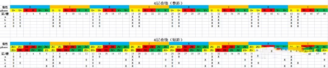
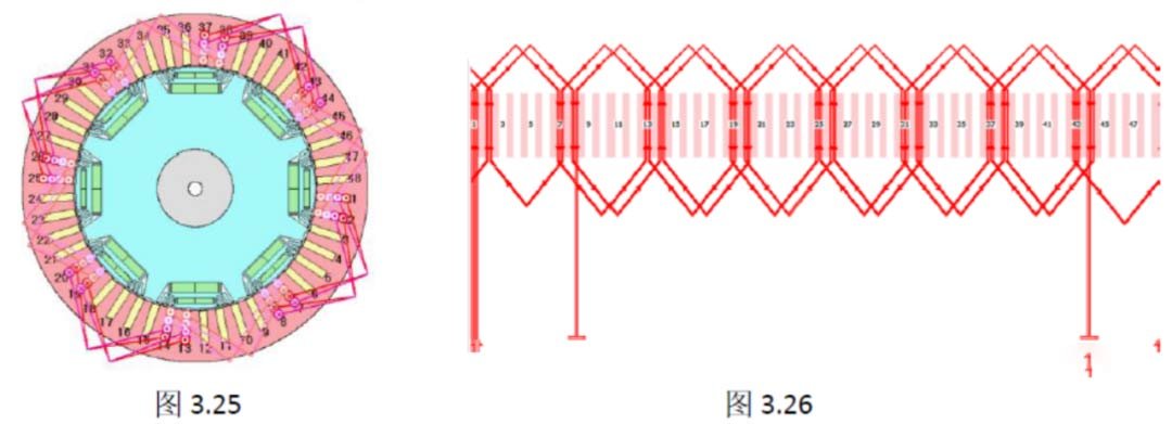
Such as (Figure 3.25) (Figure 3.26). The winding method of the four-layer wave winding is similar to that of the double-layer, and the lower coils of the same pole are connected in series in sequence, and each advance is about a pair of pole distances. Artificially advance or retreat a slot. The U-phase branch coil path is as follows:
Branch 1:(1#a-7#b)-(13#a-19#b)-(25#a-31#b)-(37#a-43#b)-(2#a-8#b)-(14#a-208#b)-(26#a-32#b)-(38#a-44#b)
Branch 2:(1#b-7#a)-(13#b-19#a)-(25#b-31#a)-(37#b-43#a)-(2#b-8#a)-(14#b-208#a)-(26#b-32#a)-(38#b-44#a)
Branch 3:(1#c-7#d)-(13#c-19#d)-(25#c-31#d)-(37#c-43#d)-(2#c-8#d)-(14#c-208#d)-(26#c-32#d)-(38#c-44#d)
Branch 4:(1#d-7#c)-(13#d-19#c)-(25#d-31#c)-(37#d-43#c)-(2#d-8#c)-(14#d-208#c)-(26#d-32#c)-(38#d-44#c)
Summary
(1) Whether it is a 4-layer flat wire winding or a 6-layer or 8-layer winding, the winding method and principle are the same as the double-layer winding.
(2) The magnitude of the potential and the distribution coefficient of the winding have nothing to do with the connection order of the ends. When the pitch is fixed, the potential magnetism and potential of the wave winding or the stacked winding are equal.
(3) In order to ensure that the ends of the flat wire are neat and beautiful, and the lead wires are relatively concentrated, it is more conducive to the arrangement of the busbar, usually in the form of wave winding.
(4) Some manufacturers of flat wire motors use special winding methods to reduce the types of wire types, the number of bridge wires, and the number of star-angle contacts, and the process is simpler.
AIP focuses on global motor testing. The above information comes from the Internet. If there is any infringement, please contact the author to change it.