Ⅰ.Background

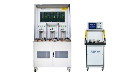
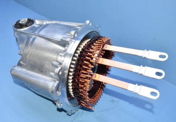
New energy vehicles are currently in a period of rapid development, product quality is rapidly improving, and consumers have higher and higher requirements for vehicle performance. Because flat wire motors have obvious advantages over round wire motors in terms of high efficiency, high power density, excellent NVH, high integration and low cost, many high-end models are equipped with flat wire motors, such as (Figure 1.1) the best-selling models The use of flat wire motors is as follows, and the penetration rate of flat wire motors is expected to be greater in 2025. For example (Figure 1.2) the 10-layer flat wire motor mounted on Tesla Model Y was first exposed last year, and flat wire technology will usher in a hot topic.
Although the flat wire has many incomparable advantages of traditional windings, at the same time, the flat wire motor also has some disadvantages and technical difficulties.
1. Large investment in equipment;
2. The increased processing difficulty (plug, wire forming, twisting, flat cutting, welding, etc.) is very different from the round wire motor process, and requires extremely high equipment accuracy and process consistency;
3. Serialization is difficult, because the number of turns of the flat wire motor is relatively fixed, it is difficult to simply increase the stack thickness to meet the needs of different products for motor performance;
4. Patent barriers.
This article mainly introduces several special winding structures in the flat wire motor patents of various manufacturers, and what innovations have been made in response to the above-mentioned pain points of flat wire motors.
In the previous article "Analysis of Flat Wire Motor Winding Technology (1)", the basic structure and principle of the winding and the basic winding scheme of the flat wire motor were mainly explained. If you have forgotten your friends, you can review them again.
Ⅱ.Second, the traditional flat wire winding structure
1. Full pitch wave winding
In order to ensure that the ends of the flat wire are neat and beautiful, the lead wires are relatively concentrated, which is more conducive to the arrangement of the busbar. It is usually in the form of wave winding. Due to the limitation of process capacity, the current domestic flat wire motor layers are mainly 4 layers, 6 layers and 8 layers. Take the 8-pole 48-slot 8-layer wave-wound flat wire motor as an example. The number of layers is numbered a-h from the outer diameter to the inner diameter. OX represents the current flow in the slot, red and blue represent two different branches, and the solid line and the dotted line represent the hairpin Crown and soldered ends of windings:
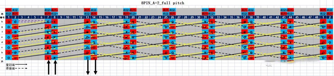
Figure 2.1
As shown in Figure 2.1, according to the winding sequence and parallel branch classification, the winding structure is A=2, and each branch has 8 sub-winding segments and 1 bridge wire.
The first branch:
First subwinding segment; (7a-13b), (19a-25b), (31a-37b), (43a-1b)
Second subwinding segment; (7c-13d), (19c-25d), (31c-37d), (43c-1d)
The third subwinding segment; (7e-13f), (19e-25f), (31e-37f), (43e-1f)
Fourth sub-winding segment; (7g-13h), (19g-25h), (31g-38h), (43g-1h)
Bridge line; (1h-8h)
Fifth sub-winding segment; (8h-2g), (44h-38g), (32h-26g), (20h-14g)
Sixth subwinding segment; (8f-2e), (44f-38e), (32f-26e), (20f-14e)
Seventh subwinding segment; (8d-2c), (44d-38c), (32d-26c), (20d-14c)
Eighth sub-winding segment; (8b-2a), (44b-38a), (32b-26a), (20b-14a)
Second branch:
First subwinding segment; (8a-14b), (20a-26b), (32a-38b), (44a-2b)
Second subwinding segment; (8c-14d), (20c-26d), (32c-38d), (44c-2d)
Third subwinding segment; (8e-14f), (20e-26f), (32e-38f), (44e-2f)
Fourth sub-winding segment; (8g-14h), (20g-26h), (32g-38h), (44g-2h)
Bridge line; (2h-7h)
Fifth sub-winding segment; (7h-1g), (43h-37g), (31h-25g), (19h-13g)
Sixth subwinding segment; (7f-1e), (43f-37e), (31f-25e), (19f-13e)
Seventh subwinding segment; (7d-1c), (43d-37c), (31d-25c), (19d-13c)
Eighth sub-winding segment; (7b-1a), (43b-37a), (31b-25a), (19b-13a)
As shown in Figure 2.1, according to the torsion direction of the welding end, there are two types of conductors;
Class I conductors; left leg twisted to the left - right leg twisted to the right, as in (19a-25b)
Class II conductor; left leg twisted to the left - right leg twisted to the left, eg (8h-2g)
As shown in Figure 2.1, according to the separation direction of the welding end, it is divided into three types of conductors;
Class 1 conductors; left leg split inward - right leg split out, as in (19a-25b)
Class II conductors; left leg split inward - right leg split inward as in (43a-1b)
Class III conductor; left leg separated outward - right leg separated outward as in (7c-13d)
summary:
(1) The windings are wound on layers a and b in a wave-like manner along the wire direction according to the pitch Y=6. After the first sub-winding segment (43a-1b) is wound, 1b cannot be connected to 7a because the subsequent layer numbers need to be wound and 7a is already occupied. Therefore, the separation direction of the welding end is changed, and the cross-layer (1b-7c) is connected and continues to be wound. The rest of the sub-winding segments are the same.
(2) After winding the fourth sub-winding segment (43g-1h), it is no longer possible to cross layers again. However, the U-phase of the even slot number has not yet started to be wound, so it is necessary to change the span, from span 6 to 7. We usually call this winding (1h-8h) a bridge wire or a special-shaped pin. After bridging, the winding direction is changed from clockwise to counterclockwise, and the remaining U1 slots are wound in the reverse direction.
(3) In the operation of actually winding the last two layers of g and h, it is not necessary to wind one circle until (43g-1h) and start bridging forward, or it can be bridged before that, such as (Figure 2.2) bridge The wiring becomes (1h-44h), and the winding can also be completed. Only the relative position of the incoming and outgoing lines changes. The 14a outgoing line becomes the 2a outgoing line. It should be noted that improper selection of the bridging position may lead to the distance between the incoming and outgoing lines, and the arrangement of the busbar is difficult. Usually only the above two methods are used. As shown in Figure 2.1, according to the winding sequence and parallel branch classification, the winding structure is A=2, and each branch has 8 sub-winding segments and 1 bridge wire.
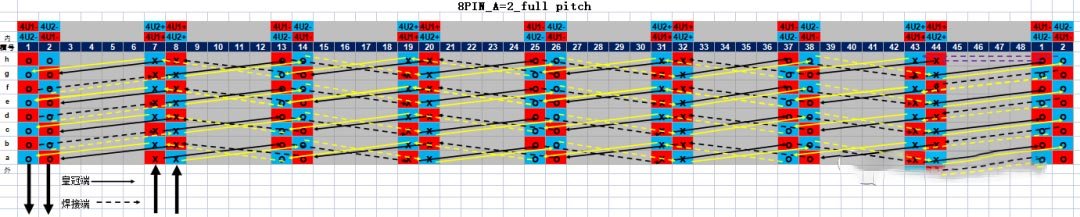
Figure 2.2
(4) In the actual winding, the crown ends should be parallel to each other, and the welding ends should be parallel to each other, such as (7a-13b), (7c-13d), (8a-14b), to avoid different layers Cross-soldering will cause interference between pins.
(5) This winding structure is also suitable for the number of parallel branches A=1, 4. For example (Fig. 2.1) only need to connect (14a-8a), then it becomes A=1; or if the bridge wire is disconnected, and the outlet end 1h and the inlet end 8h are added, it becomes A=4
(6) Similarly, this winding structure can also be wound in the counterclockwise direction, such as (7a-1b); since the special-shaped pin will occupy the radial space, the a-h layers can also be reversed, from the outer outlet to the inner outlet; the dotted line can also be used. The solid line is reversed, and the outgoing line is changed from the crown end to the welding end.
2. Short-distance wave winding
In order to effectively weaken the fifth and seventh harmonics, the short-distance winding method is usually used in practical applications, as shown in Figure (2.3), the span of one side of the coil is Y1=7, the span of the other side is Y2=5, and the combined pitch Y= Pole distance 2τ=48/4=5+7=12.
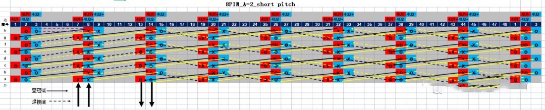
Figure 2.3
For example (Figure 2.3), according to the winding sequence and parallel branch classification, the winding structure is A=2, and each branch has 8 sub-winding segments and 1 bridge wire.
The first branch:
First subwinding segment; (7a-14b), (19a-26b), (31a-38b), (43a-2b)
Second subwinding segment; (7c-14d), (19c-26d), (31c-38d), (43c-2d)
Third subwinding segment; (7e-14f), (19e-26f), (31e-38f), (43e-2f)
Fourth sub-winding segment; (7g-14h), (19g-26h), (31g-38h), (43g-2h)
Bridge line; (2h-8h)
Fifth sub-winding segment; (8h-1g), (44h-37g), (32h-25g), (20h-13g)
Sixth subwinding segment; (8f-1e), (44f-37e), (32f-25e), (20f-13e)
Seventh subwinding segment; (8d-1c), (44d-37c), (32d-25c), (20d-13c)
Eighth sub-winding segment; (8b-1a), (44b-37a), (32b-25a), (20b-13a)
Second branch:
First subwinding segment; (8a-15b), (20a-27b), (32a-39b), (44a-3b)
Second subwinding segment; (8c-15d), (20c-27d), (32c-39d), (44c-3d)
Third subwinding segment; (8e-15f), (20e-27f), (32e-39f), (44e-3f)
Fourth sub-winding segment; (8g-15h), (20g-27h), (32g-39h), (44g-3h)
Bridge line; (3h-9h)
Fifth sub-winding segment; (9h-2g), (45h-38g), (33h-26g), (21h-14g)
Sixth subwinding segment; (9f-2e), (45f-38e), (33f-26e), (21f-14e)
Seventh subwinding segment; (9d-2c), (45d-38c), (33d-26c), (21d-14c)
Eighth sub-winding segment; (9b-2a), (45b-38a), (33b-26a), (21b-14a)
For example (Figure 2.3), according to the torsion direction of the welding end, there are two types of conductors;
Class I conductors; left leg twisted to the left - right leg twisted to the right, as in (19a-26b)
Class II conductor; left leg twisted to the left - right leg twisted to the left, eg (8h-1g)
As shown in Figure 2.3, according to the separation direction of the welding end, it is divided into three types of conductors;
Class 1 conductors; left leg separated inwards - right leg separated outwards, as in (19a-26b)
Class II conductor; left leg split inward - right leg split inward as in (43a-2b)
Class III conductors; left leg out - right leg out, as in (7c-14d)
summary:
(1) The short-pitch winding cross-layer method is similar to the full-pitch winding. The same is to change the separation direction of the welding end after one turn is completed, and the cross-layer wires (3b-8c) are connected and continue to be wound.
(2) The short-distance winding bridging method is similar to the full-distance winding. After the fourth sub-winding segment (44g-3h) is wound, the span is changed from span 5 to 6, and the winding direction is changed from clockwise to reverse. Hour hand, reverse and continue to wind the remaining U1 slot.
(3) As (Figure 2.4), the same short-distance winding can also be bridged forward at (43g-2h), and the bridge line becomes (2h-44h).
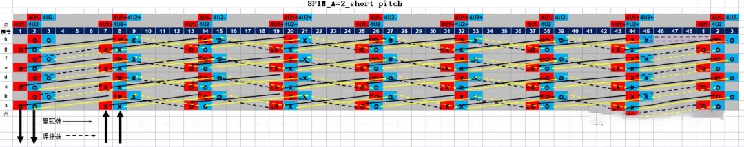
(4) In the same way, the crown ends should be parallel to each other, and the welding ends should be parallel to each other to avoid cross welding of different layers, which will cause interference between the pins.
(5) In the same way, the winding structure can also be changed to A=1, 4; from clockwise winding to counterclockwise winding; from outer outlet to inner outlet; from crown end outlet to welding end outlet .
(6) Due to the short-distance winding, not every slot has the same phase between different layers. For example, the phases between 7a and 7b are U+ and W-, respectively. Then there is a large potential difference between layers, for high voltage systems. Higher requirements for insulation.
Ⅲ.Songzheng-CN202010958051
This patent introduces a mixed wave winding scheme of long and short pitch and long full pitch or short full pitch windings. It is characterized in that: the pitch between the two welded ends of the conductors of the Mth layer and the M+1th layer adjacent to the stator core in the radial direction is a short pitch or a long pitch. The pitch between the two welded ends of the conductors of two adjacent layers is a full pitch. Take 8 poles 48 slots 6pin, A=2 as an example, such as (Figure 3.1)
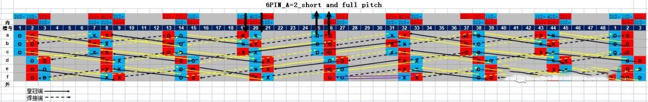
Figure 3.1
According to the winding sequence and parallel branch classification, the winding structure is A=2, and each branch has 6 sub-winding segments and 1 bridge wire.
first branch
First subwinding segment; (13b-8a), (2b-43a), (37b-32a), (26b-19c)
Second subwinding segment; (14d-8c), (3d-43c), (38d-32c), (27d-21e)
The third sub-winding segment; (15f-8e), (2f-45e), (39f-32e)
Bridge wire: (26f-33f)
Fourth subwinding segment; (39e-44f), (2e-9f), (15e-20f), (26e-32d)
Fifth subwinding segment; (37c-45d), (2c-8d), (13c-21d), (26c-31b)
Sixth subwinding segment; (37a-44b), (2a-7b), (13a-20b)
second branch
First subwinding segment; (14b-7a), (1b-44a), (38b-31a), (25b-20c)
Second subwinding segment; (15d-7c), (2d-44c), (39d-31c), (26d-20e)
The third sub-winding segment; (14f-9e), (3f-44e), (38f-33e)
Bridge wire; (27f-32f)
Fourth subwinding segment; (38e-45f), (3e-8f), (14e-21f), (27e-33d)
Fifth subwinding segment; (38c-44d), (1c-9d), (14c-20d), (25c-32b)
Sixth subwinding segment; (38a-43b), (1a-8b), (14a-19b)
According to the different torsion direction of the welding end, it is divided into two categories;
Left leg twisted to the left - right leg twisted to the right as in (13b-8a)
The separation direction of the welding ends is the same;
Left leg separates inwards - right leg separates outwards as in (13b-8a)
summary:
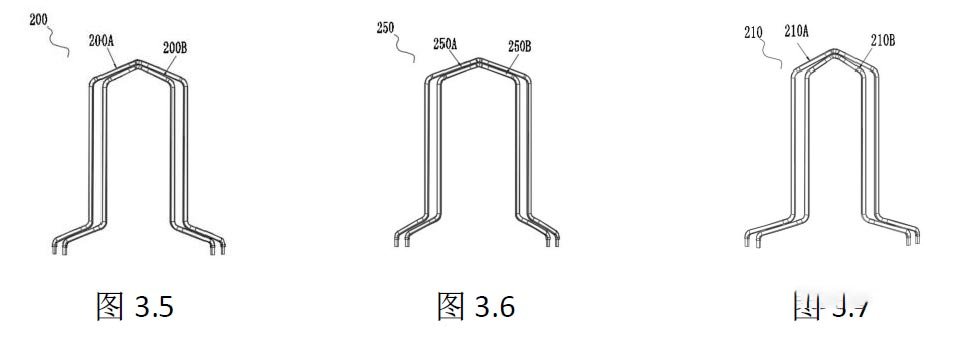
(1) For example (Fig. 3.2) long and short pitch windings refer to: between layers a and b or between layers e and f, the crown end adopts two formed conductors, such as (Fig. 3.5) long pitch conductor 200A is set in Outside the pitch conductor 200B, the pitch of the long pitch conductor 200A is 7, and the pitch of the short pitch conductor 200B is 5.
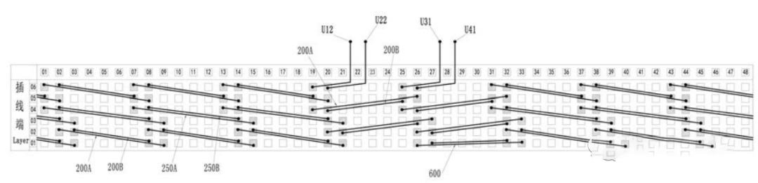
Figure 3.2 Crown end connection
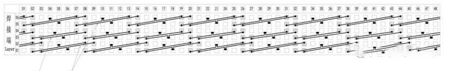
Figure 3.3 Soldering terminal connection
(2) For example (Fig. 3.2) the long-pitch winding refers to: between layers c and d, the crown end adopts two kinds of forming conductors, such as (Fig. 3.6) the long-pitch conductor 250A is set outside the full-pitch conductor 250B, The pitch of the long pitch conductors 250A is 8 and the pitch of the full pitch conductors 250B is 6.
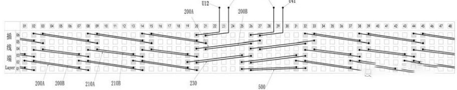
Figure 3.4 Crown end connection (deformation)
(3) If (Fig. 3.4) this winding structure can change the d, e, and f phases from clockwise to counterclockwise, then the c and d layers of long full-pitch windings become full short-pitch, such as (Fig. 3.7 ) The full-pitch conductors 210A are arranged outside the full-pitch conductors 210B, the pitch of the long-pitch conductors 210A is 8, and the pitch of the full-pitch conductors 210B is 6.
(4) As shown in Figure 3.4, the winding structure can reverse the phases of 26d and 27d, 32d and 33d, and 32f and 33f, and the bridge wire can be connected by a concentric structure to a full-pitch structure.
(5) The characteristic of this winding structure is that the twisting process and the separation process are relatively simple. Except for the bridge wire, the other slot windings are the left leg twisted to the left, the right leg twisted to the right, and the left leg separated inward - the right leg to the left. external separation. However, due to the different spans of crown ends, this structure increases the types of conductors, and the difficulty of wiring is relatively complicated compared with the traditional winding structure.
(6) The winding structure is not symmetrical at 45° mechanical angle on the magnetic circuit, but is symmetrical along 180°. Therefore, A=1 cannot be used, and the minimum number of parallel branches is 2. When A=2, 4, the structure eliminates the loop current problem caused by asymmetry, reduces torque fluctuation, reduces harmonics, and reduces noise.
Ⅳ.Evergrande-CN202111037524
This patent describes a hybrid stacking scheme for long-pitch and full-pitch windings. It is characterized in that: the windings are under the same branch, the innermost layer and the outermost layer of the coils are in the same layer, and the middle layer is in different layers. Take 8 poles 48 slots 8pin, A=2 as an example, such as (Figure 4.1, Figure 4.2, Figure 4.3)
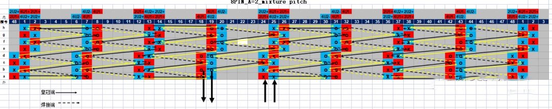
Figure 4.1
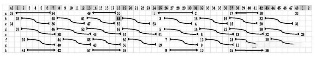
Figure 4.2 U1 crown terminal connection
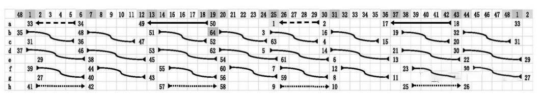
Figure 4.3 U2 crown end connection
According to the winding sequence and parallel branch classification, the winding structure is A=2, and each branch has a total of 8 sub-winding segments;
first branch
The first subwinding segment; (24a-31a), (25b-31c), (25d-32e), (26f-32g), (26h-32h)
Second sub-winding segment; (38g-32f), (38e-31d), (37c-31b)
Third subwinding segment; (37a-42a), (36b-42c), (36d-43e), (37f-43g), (37h-43h)
Fourth subwinding segment; (1g-43f), (1e-43d), (48c-42b)
Fifth subwinding segment; (48a-7a), (1b-7c), (1d-8e), (2f-8g), (2h-8h)
Sixth subwinding segment; (14g-8f), (14e-7d), (13c-7b)
Seventh subwinding segment; (13a-18a), (12b-18c), (12d-19e), (13f-19g), (13h-19h)
Eighth sub-winding segment; (25g-19f), (25e-18d), (24c-18b)
second branch
The first sub-winding segment; (25a-30a), (24b-30c), (24d-31e), (25f-31g), (25h-31h)
Second subwinding segment; (37g-31f), (37e-30d), (36c-30b)
Third subwinding segment; (36a-43a), (37b-43c), (37d-44e), (38f-44g), (38h-44h)
Fourth sub-winding segment; (2g-44f), (2e-43d), (1c-43b)
Fifth subwinding segment; (1a-6a), (48b-6c), (48d-7e), (1f-7g), (1h-7h)
Sixth subwinding segment; (13g-7f), (13e-6d), (12c-6b)
Seventh subwinding segment; (12a-19a), (13b-19c), (13d-20e), (14f-20g), (14h-20h)
Eighth sub-winding segment; (26g-20f), (26e-19d), (25c-19b)
There are three types of conductors according to the number of spans:
The first type of conductor; Y=6 equal distance, such as (25b-31c)
The second type of conductor; Y=5 short distance, such as (37a-42a)
The third type of conductor; Y=7 long distance, such as (25d-32e)
There are two types of conductors according to the torsion direction of the welding end;
Class 1 conductor; left leg twisted left - right leg twisted left as in (37a-42a)
Class II conductor; left leg twisted to the right - right leg twisted to the left, as in (25b-31c)
Class III conductor; left leg twisted to the right - right leg twisted to the right, eg (26h-32h)
It is divided into three types of conductors according to the different separation directions of the welding ends;
Class 1 conductors; left leg split in - right leg split inward as in (37a-42a)
Class II conductor; left leg separated outward - right leg separated inward, as in (25b-31c)
Class III conductor; left leg separated outward - right leg separated outward, eg (26h-32h)
Summary:
(1) As shown in (Fig. 4.1, Fig. 4.2, Fig. 4.3) in this stacked structure, the coils on the a and h layers are in the same layer, and the coils in the other layers are in different layers, and the coils in the same layer are in the same layer. The coils are arranged at intervals, and the coils of different layers across the line are arranged continuously.
(2) As (Fig. 4.1, Fig. 4.2, Fig. 4.3), the stacked winding structure is distributed at an interval of 5 and 7 in the a and h layers; the span in the d and e layers is 7; in b, c and f , The span of the g layer is 6; the long-distance, short-distance and full-distance mixing schemes are realized. Therefore, the harmonic electromotive force can be effectively weakened, the magnetic potential waveform can be improved, the additional loss caused by the harmonic can be reduced, and the motion noise generated by the winding during operation can be improved.
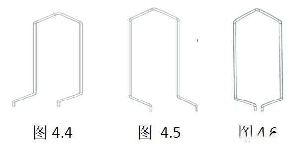
(3) The shape of the conductor after the twisting of this winding structure is different from that of the traditional wave winding, and the two legs of the conductors in layers a and h are twisted in the same direction (as shown in Figure 4.4 and Figure 4.5), and the two legs of the conductors in the other layers are both twisted in the same direction. It is twisted inward (as shown in Figure 4.6), the advantage is that the span of the welded ends is 6, and there is no bridge wire. It can effectively reduce the height of the welding end winding.
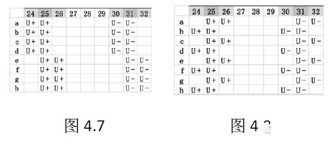
(4) If (Fig. 4.7, Fig. 4.8) 24-slot, 26-slot U+ can be changed from unilateral distribution to staggered distribution, the winding wiring diagram is shown in (Fig. 4.9, Fig. 4.10, Fig. 4.11), and layers a and h can be made. All of them become full pitch, but the number of layers across the middle layer of the U1 and U2 outlet ends and the welding end will be different, which may cause different resistances, resulting in uneven current distribution.
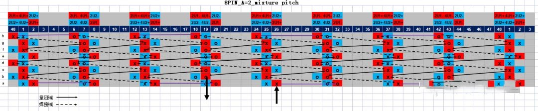
Figure 4.9
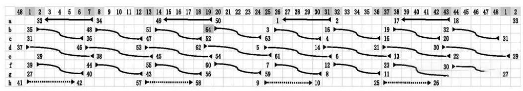
Figure 4.10
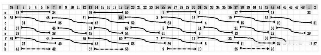
Figure 4.11
(5) The characteristic of this winding structure is that the welding end span is 6, and there is no bridge wire. Also, due to the different spans of the crown ends, the types of conductors are increased, and the difficulty of wiring is relatively complicated compared with the traditional winding structure.
Ⅴ.BYD-CN201810850677.2
In this patent, a wave winding scheme with a spanning layer number > 1 is introduced. It is characterized in that: the winding structure is divided into a first type of conductor segment and a second type of conductor segment according to the number of layers across. The two legs of the first type of conductor segment are located at the innermost layer and the outermost layer respectively, and the two legs of the second type of conductor segment are located at the sub-inner layer and the sub-outer layer respectively. The intermediate connection part of the first type of conductor segment is sheathed over the intermediate connection part of the second type of conductor segment, as shown in (Figure 5.1)
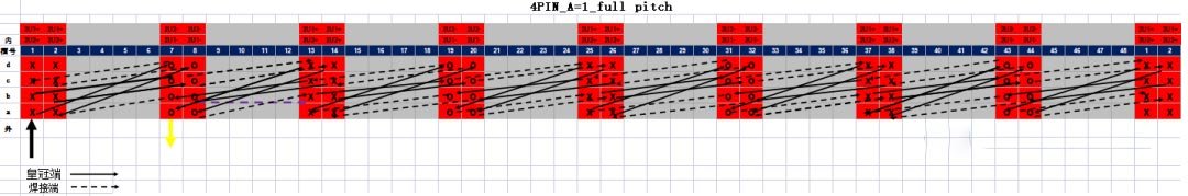
Figure 5.1
According to the winding order, a total of 4 sub-winding segments
First sub-winding segment; (1a-7d), (1c-43b), (37a-43d), (37c-31b), (25a-31d), (25c-19b), (13a-19d), (13c -7b)
Second subwinding segment; (2a-8d), (2c-44b), (38a-44d), (38c-32b), (26a-32d), (26c-20b) (14a-20d), (14c- 8b)
Bridge line; (8b-14b)
Third subwinding segment; (14b-20c), (26d-20a), (26b-32c), (38d-32a), (38b-44c), (2d-44a), (2b-8c), (14d) -8a)
Fourth sub-winding segment; (13b-19c), (25d-19a), (25b-31c), (37d-31a), (37b-43c), (1d-43a), (1b-7c), (13d -7a)
According to the number of layers across, it is divided into two types of conductors;
The first type of conductor; a (outermost layer)-d (innermost layer), such as (1a-7d)
The second type of conductor; b (sub-outer layer)-c (sub-inner layer), such as (1c-43b)
There are two types of conductors according to the torsion direction of the welding end;
Class 1 conductor; left leg twisted to the left - right leg twisted to the right, as in (1c-43b)
Class II conductor; left leg twisted to the right - right leg twisted to the left, as in (37a-43d)
It is divided into three types of conductors according to the different separation directions of the welding ends;
Class 1 conductors; left leg separated outward - right leg separated inward, as in (1c-43b)
Class II conductor; left leg separated inward - right leg separated outward as in (37a-43d)
summary:
(1) As shown in Figure 5.1, the winding adopts the wave-wound wiring method and combines the adjustment of the span of some welding ends. The voltage distribution in the same slot is relatively uniform, and the voltage difference between the adjacent layers of the flat wire is small, which can effectively reduce the Risk of motor insulation breakdown.
(2) As shown in (Fig. 5.2, Fig. 5.3) there are 3 protrusions (262, 263, 264) in the neutral wire (260) of the winding, wherein (262) is welded with the U-phase (252A), and (263) is welded with the U-phase (252A). W-phase (252W) welding, (264) and V-phase (252B) welding.
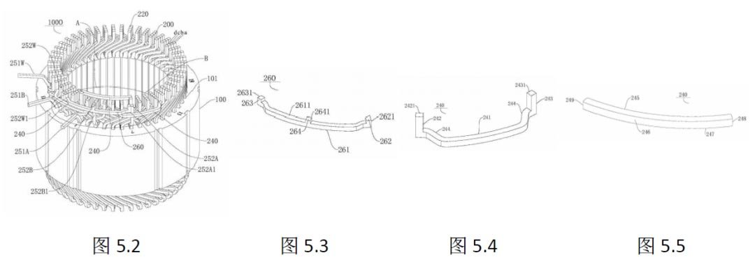
(3) As shown in (Fig. 5.2, Fig. 5.4, Fig. 5.5), the winding bridge wire (240) includes three-phase U, V, W bridge wires (240A, 240B, 240W), and the bridge wire can be made into a U-shaped structure For example (Fig. 5.4), a raised structure is used to weld with the welding end (220), or a straight line can be made (Fig. 5.5)
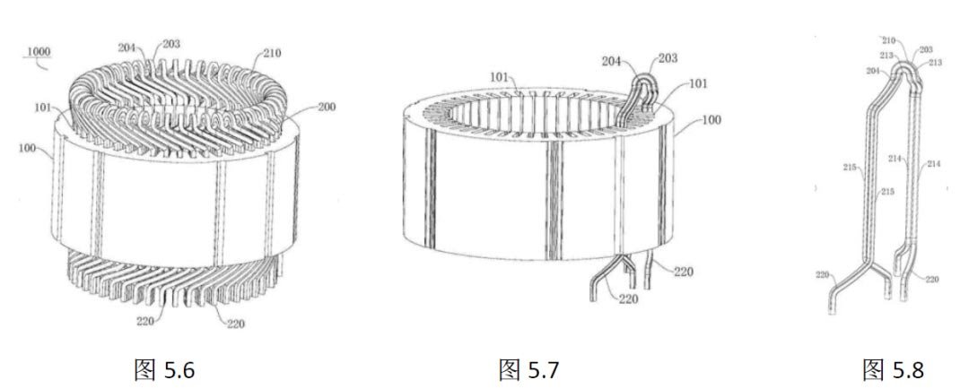
(4) The crown ends of the traditional flat wire motor should be parallel to each other, and the welding ends should also be parallel to each other. However, in this winding structure, the number of layers across is greater than 1 through the nose structure. Such as (Figure 5.6, Figure 5.7, Figure 5.8). The intermediate connection part (213) of the first type conductor (203) is sheathed with the intermediate connection part (213) of the second type conductor (204), and the two types of conductors (213) The end projections are completely coincident.
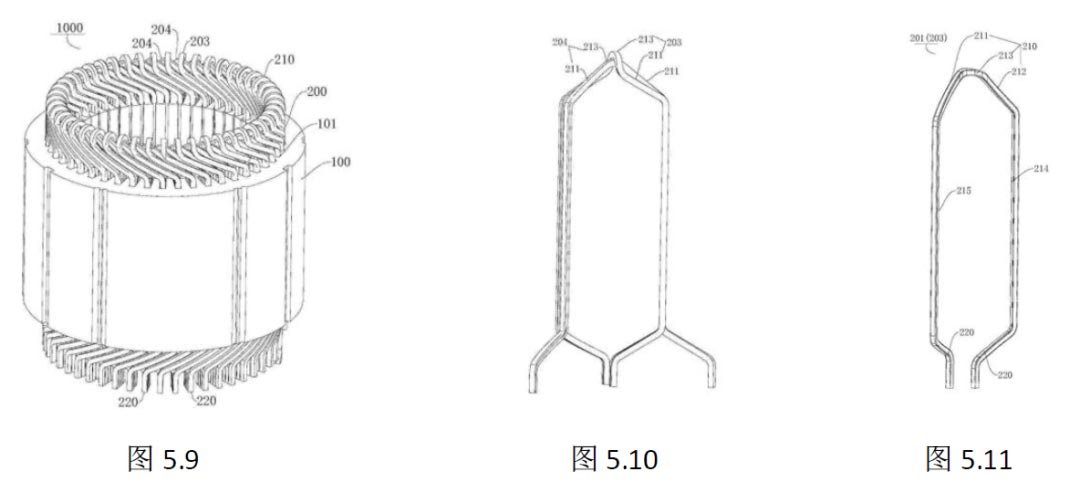
(5) The nose structure can be deformed as follows (Figure 5.9, Figure 5.10, Figure 5.11). The middle connection part (213) of the second type of conductor (204) is changed to a flat head structure, which can reduce the height of the coil.
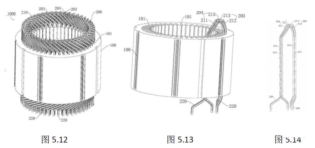
(6) The nose structure can be deformed as follows (Fig. 5.12, Fig. 5.13, Fig. 5.14). The intermediate connecting parts (213) of the first and second types of conductors (204) can be changed to a flat head structure, which can further reduce the height of the coil .
(7) It can be found that this winding structure is suitable for motors with fewer layers. If there are too many layers, it will lead to a higher height. And this structure has extremely high requirements on the difficulty and consistency of pin line forming.
Ⅵ.Summary
Whether it is a traditional winding structure or a special winding structure, each has its own merits. Motor manufacturers need to better combine their own equipment and process capabilities in order to find the most suitable answer. There is also the issue of patent ownership. According to the editor's understanding, most of the flat wire motor patents belong to Europe, America and Japan. Due to the high requirements of winding theory for winding patents, although a large number of domestic patents for flat wires can be found on the patent website, the quality is also uneven, and many of them have been applied by other companies. Several patents mentioned above , but also for everyone to learn and reference, to expand ideas.
AIP focuses on global motor testing. The above information comes from the Internet. If there is any infringement, please contact the author to change it.