
-
Test Solutions
-
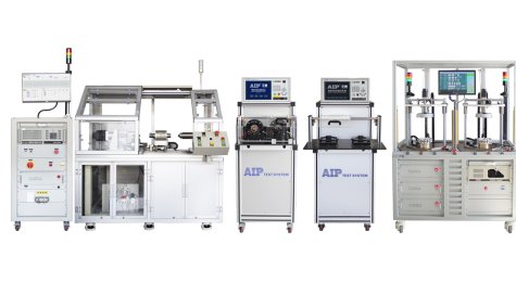
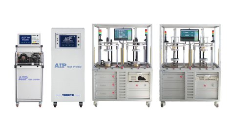
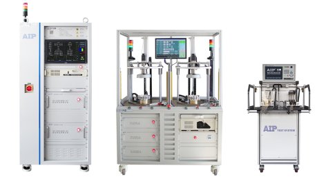
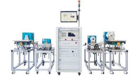
Robot Frameless Torque Motor Test Solutions
Robot Frameless Torque Motor Test Solutions

-
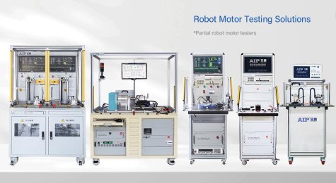
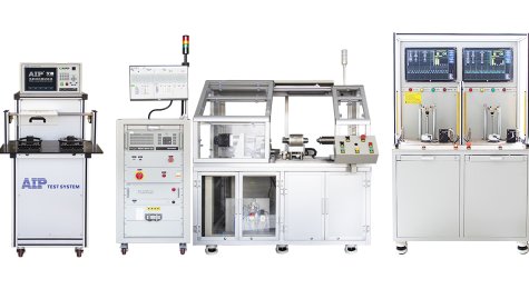
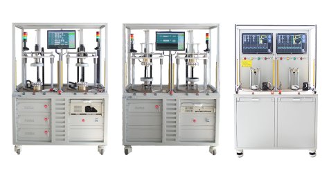
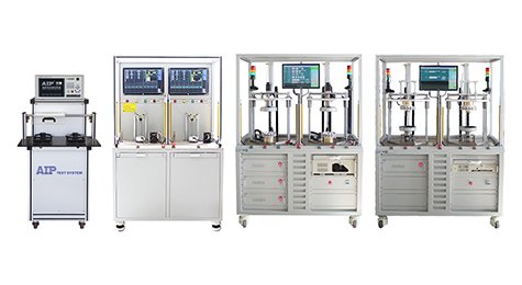
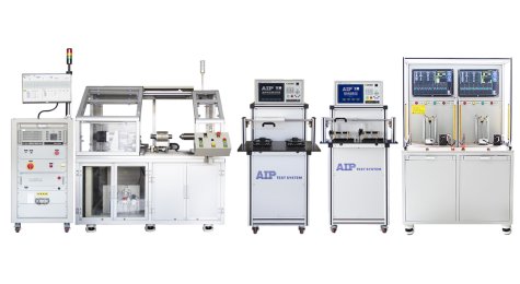
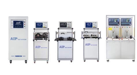
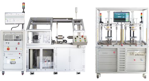
Robot Motor Test Solutions
Robot Motor Test Solutions
-
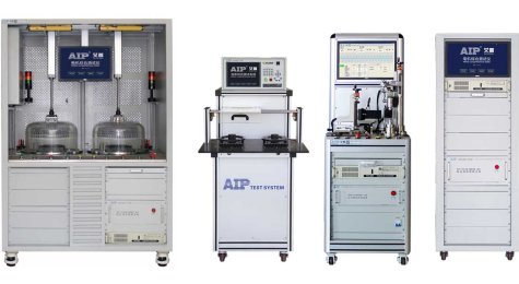
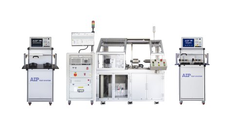
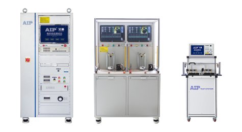
Electric Vehicle Motor Test Solutions
Electric Vehicle Motor Test Solutions
-
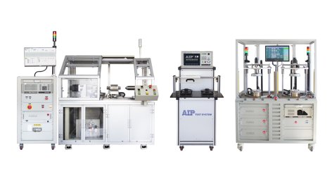
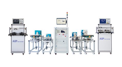
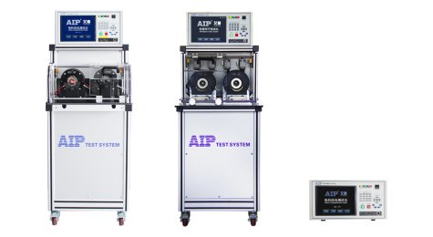
Electric Bike Motor Test Solutions
Electric Bike Motor Test Solutions
-
Automotive Motor Test Solutions
Automotive Motor Test Solutions
-
Motor automation test solutions
Motor automation test solutions
-
Air Conditioner Fan Motor Test Solutions
Air Conditioner Fan Motor Test Solutions
-
Fan Motor Test Solutions
Fan Motor Test Solutions
-
Compressor Motor Stator Test Solutions
Compressor Motor Stator Test Solutions
-
Washing Machine Motor Test Solutions
Washing Machine Motor Test Solutions

-
Power Tool Motor Test Solutions
Power Tool Motor Test Solutions
-
Small Appliance Motor Test Solutions
Small Appliance Motor Test Solutions
-
Industry Motor Test Solutions
Industry Motor Test Solutions
-
Pump Motor Test Solutions
Pump Motor Test Solutions
-
Industrial Fan Motor Test Solutions
Industrial Fan Motor Test Solutions
-
Servo Motor Test Solutions
Servo Motor Test Solutions
-
Dynamometer Test Solutions
Dynamometer Test Solutions
-
Safety Test Solution
Safety Test Solution
-
Robot Frameless Torque Motor Test Solutions
-
Products
-
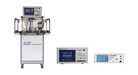
Stator Tester
Stator Tester
-
Rotor Tester
Rotor Tester
-
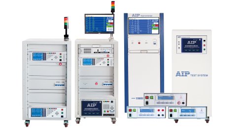
Electric Motor Tester
Electric Motor Tester
-
Armature Tester
Armature Tester
-
Dynamometer
Dynamometer
-
Safety Tester
Safety Tester
-
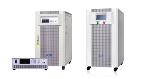
Power Source
Power Source
-
Coil tester
Coil tester
-
FCT
FCT
-
Stator Tester
- Technical Support
- News
- About Us
- Contact Us